PWM Class Reference
The basic PWM function. More...
#include <hw_pwm.h>
Collaboration diagram for PWM:
Public Member Functions | |
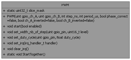
| PWM (uint gpio_ch_A, uint gpio_ch_B, int step_ns, int period_us, bool phase_correct=false, bool ch_A_inverted=false, bool ch_B_inverted=false) | |
| Construct a new PWM object assuming free running sys_clk @125 MHz => sys_clk_period = 8 ns PERIOD = 8ns * (TOP+1)*(CSR_PH_CORRECT + 1)*(DIV_INT + (DIV_FRAC/16)) or PERIOD = 8ns * (TOP+1)*(CSR_PH_CORRECT + 1)* DIV) with DIV = step_ns/8 TOP = (period_us * 1000 /(ph*step_ns)) -1 This means the minimum step_ns is 8 ns and the maximum is 256*8ns = 2.048 us the maximum period is 2.048us*64536 = 132 ms. | |
| void | start (bool enabled) |
| start and stop the current PWM slice | |
| void | set_width_nb_of_step (uint gpio_pin, uint16_t level) |
| Set the pulse width in terms number of step object. | |
| void | set_duty_cycle (uint gpio_pin, float duty_cycle) |
| Set the pulse width in terms of duty cycle. | |
| void | set_irq (irq_handler_t handler) |
| Set the irq handler, executed each time the PWM counter wrap to 0. | |
| void | clear_irq () |
| clear the slice IRQ | |
Static Public Member Functions | |
| static void | StartTogether () |
| All the defined PWM slices will be synchronised. | |
Static Public Attributes | |
| static uint32_t | slice_mask = 0x0 |
| a class variable that hold the slice number for the PWM object | |
Private Attributes | |
| uint8_t | slice |
| the hardware PWM slice of the Pico that handle this PWM signal | |
| uint | step_ns |
| the minimal pulse provided by the PWM | |
| uint | period_us |
| the period of the signal provided by PWM | |
Detailed Description
The basic PWM function.
Constructor & Destructor Documentation
◆ PWM()
| PWM::PWM | ( | uint | gpio_ch_A, |
| uint | gpio_ch_B, | ||
| int | step_ns, | ||
| int | period_us, | ||
| bool | phase_correct = false, | ||
| bool | ch_A_inverted = false, | ||
| bool | ch_B_inverted = false ) |
Construct a new PWM object assuming free running sys_clk @125 MHz => sys_clk_period = 8 ns PERIOD = 8ns * (TOP+1)*(CSR_PH_CORRECT + 1)*(DIV_INT + (DIV_FRAC/16)) or PERIOD = 8ns * (TOP+1)*(CSR_PH_CORRECT + 1)* DIV) with DIV = step_ns/8 TOP = (period_us * 1000 /(ph*step_ns)) -1 This means the minimum step_ns is 8 ns and the maximum is 256*8ns = 2.048 us the maximum period is 2.048us*64536 = 132 ms.
- Parameters
-
gpio_ch_A channel A of the current PWM slice gpio_ch_B channel B=A+1 of the current PWM slice. May be configured as Input step_ns the minimal pulse provided by the PWM period_us the period of the signal provided by PWM phase_correct true if we want the channels symmetric. ch_A_inverted true is we want channel A to be active LO ch_B_inverted true is we want channel B to be active LO
Member Function Documentation
◆ set_duty_cycle()
| void PWM::set_duty_cycle | ( | uint | gpio_pin, |
| float | duty_cycle ) |
Set the pulse width in terms of duty cycle.
- Parameters
-
gpio_pin the related pin duty_cycle the required duty cycle
◆ set_irq()
| void PWM::set_irq | ( | irq_handler_t | handler | ) |
Set the irq handler, executed each time the PWM counter wrap to 0.
- Parameters
-
handler
◆ set_width_nb_of_step()
| void PWM::set_width_nb_of_step | ( | uint | gpio_pin, |
| uint16_t | level ) |
Set the pulse width in terms number of step object.
- Parameters
-
gpio_pin the related pin level the required number of steps
◆ start()
| void PWM::start | ( | bool | enabled | ) |
start and stop the current PWM slice
- Parameters
-
enabled
The documentation for this class was generated from the following files:
- hw_pwm.h
- hw_pwm.cpp